Place the LED so that the anode, +, connection is connected to the pin on the switch. Now place the LED in the circuit between the 470 ohm resistor and the right pin of the switch. If you did not have long legs on you resistor you will need to bridge the gap in a similar way that we did with the IC sockets and the voltage rails. If you had long legs on your resistor bend one now so that it touches the switch connection. Now you will need to bridge the gap between the 10K resistor and the switch. If you have a switch with 4 pins make sure you place it so that the connection will be broken between the left and right set of pins. Place the switch with one pin farthest to the left so that it aligns vertically with the resistor. The switch will provide positive power to the 10K ohm resistor. Now to place the switch and LED in the circuit.


Take a look at the final solder layout in step 6 of this Instructable if you are still having trouble. Go slow so that you do not bridge pins that you would not want to connect. Remember you are only connecting 4 pins! NOTE: I would show a picture of the pins bridged but I did not bridge them until I was building each test circuit.

Now touch both the IC socket pin and the voltage rail with the soldering iron tip and apply more solder until the connection is made. To bridge the gap solder the IC socket in and then place a bit of solder on the voltage rail closest to the pin. See the pictures for a better explanation. While soldering the sockets in place bridge the gap between the following pins and the nearest voltage rail. Starting from the left, pins 1 and pins 6 top and bottom. This spacing will allow us to run wire later so the we can provide power to the testing circuits. The other socket is place two spaces next to the first socket. Place the first socket one space from the left of the prototype board. Two 8 pin IC sockets are used to hold the transistors as we test them. I have gone through about 100 transistors that were pulled from old electronics and have never found any other orientations so i have found that there is no need to test for anything but these two orientations. The emitter pin is again on the left but the middle pin is the collector and the right pin is the base. ECB similar to the above acronym stands for Emitter Collector Base. When I use this acronym I am saying that the pin to the left is the emitter, the middle pin is the base, and the right pin is the collector.

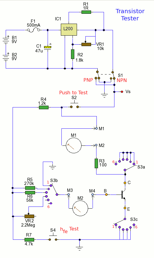
That is probably not the official way to classify them but it makes more sense to me when I am placing them in a circuit. I define the pin layout when looking at the top of the transistor with the flat side facing toward you. The orientation of the transistor is the pin layout. The transistor type NPN/PNP determines the polarity of the connections. I find myself testing a lot of transistors to determine their pin layout and type and as such find that building the test circuit on a breadboard has become a hassle so I wanted an easy circuit that would be more permanent and would allow me to test transistors. The purpose of this circuit is to test NPN and PNP transistors and to identify their pin layouts, ie ECB, EBC.


 0 kommentar(er)
